Print out and keep this step-by-step guide to installing a Space Saver plinth heater.
Intended for installation at the foot of kitchen cabinets behind the plinth, the Space Saver Plinth Heater is a cost effective and energy efficient heating solution, using only 5% of the water capacity of a radiator with an equivalent output. Acting as a compact alternative to panel radiator designs, the heater is an ideal product if space is at a premium.
Space Saver can be used for domestic and commercial applications and is available in a range of models to suit varying room sizes and heat outputs.
The electrical connection should be via a 3A double pole fused spur. The fused spur must not be directly above the heater but needs to be accessible after completion of the installation. It is important to ensure adequate airflow so a minimum clearance of 20mm between the top of the product and any shelving is essential.
To avoid the possibility of any vibration during operation, the Space Saver must be installed on a flat, even surface and there must be no rear access to the Space Saver after the installation is complete. A remote room thermostat can be used in conjunction with the Space Saver Plinth Heater. The Space Saver is manufactured by Smith’s Environmental Products and now distributed by Robert Lee.
Before starting
Step 1 - Cut the opening in the kitchen plinth to the appropriate size
Step 2 - Clean and deburr the heater and system flow and return pipes. Not doing so can damage the seal in the flexible hose connections and lead to water leaks
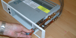
Step 3 - Connect the flexible hoses to the heater flow and return pipes
Step 4 - Connect the other ends of the flexible hoses to the heating system flow and return pipes. Isolating service valves should be added at the most accessible point. System flow and return pipes to the heater must, where possible, be the same level or below the heater’s own flow and return pipes. This will reduce the risk of air traps. If this cannot be avoided ensure that a finger vent is fitted, allowing any air traps to be vented. Then, open the valves and check for leaks
Step 5 - Vent air from the system via the bleed screw, then isolate the electrical supply. Connect the heater electric cable to the 3A fused spur. The fused spur must not be directly above the heater and it must be accessible after completion of the installation.
This feature ran in the November/December issue of HVP.
If you'd like to keep up-to-date with the latest developments in the heating and plumbing industry, why not subscribe to our weekly newsletters? Just click the button below and you can ensure all the latest industry news and new product information lands in your inbox every week.
Subscribe to receive your free copy of HVP every month.